|
The 21A Cooling Fan Assembly Service and How-To Tips for the Oil Filled Fan Assembly |
|||||
|
|
|||||
| Home Parts Drawings Web Links Tune-Up & Service Serial Numbers Engine ID Trans ID Model Identification Terms of Sale Contact Us Our Online Store Our Catalog | |||||
|
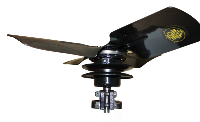
When Ford decided to change the flathead V8 engine fan design for 1942, they developed a design that moved the fan to a mid level location on the motor. It was felt that this provided the maximum air flow through the heart of the radiator, and over the engine itself. The fan design was simple enough, a steel shaft running through a machined casting on a film of oil. The shaft had a slinger-impeller on its forward end, which tossed the lubricant back over the bearing structure where holes in the casting of the spindle bearing allowed the oil to reach the rotating shaft. The fan design worked well enough that Ford used it for a number of years. The following V8 vehicles used this fan:
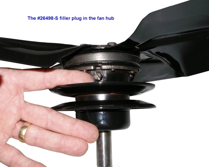
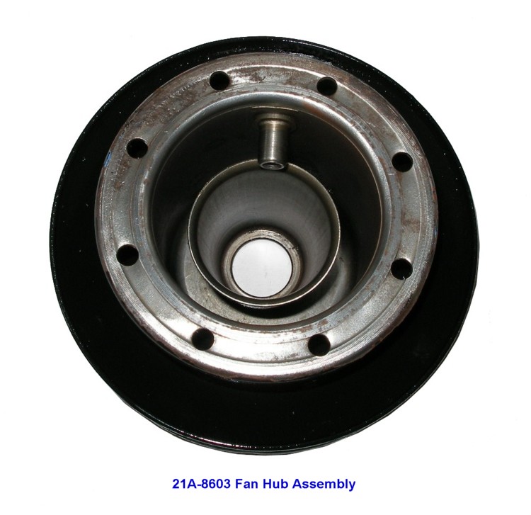
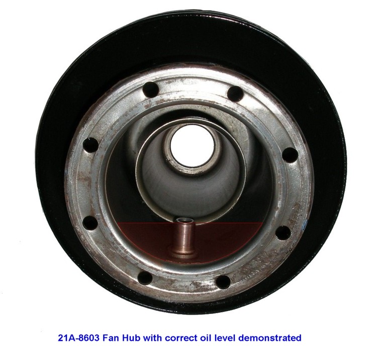
If there is one flaw in the fan, it is this. Over many years of service, plus the lack of service knowledge on them, future owners of such vehicles are not aware of the need of lubrication of this component. Owners manuals are often lost, and the maintenance tips were never passed on to the next owner. This happens whether the engine remained in a stock vehicle or if the motor was removed and installed in a hot rod. So, what happens if the fan is not lubricated? Eventually, one of two things will occur. Either the fan shaft runs dry and seizes in its spindle bearing, thus stopping the fan from rotating and burning up the fan belt. Or, in a worst case scenario, the shaft overheats and breaks while the engine is running. This allows the fan and its hub to separate from the mount, and causing untold damage to the radiator or other engine accessory components. So what do you do? First make sure that you have this type fan on your flathead V8. They are easily identified by the eight bolts that attach the fan itself to the hub/carrier assembly. The hub is larger in diameter than any other Ford fan mounts, and the mounting bracket attaches to the front side of the generator mounting bracket. The pictures below will easily show what this unit looks like. Your next step (assuming your fan still spins freely) is to lubricate the hub. With a clean rag, wipe the hub in the area just behind the fan blade. You will see a small straight slotted screw. This is the filler AND the drain plug! Rotate your fan and hub until the filler plug is up (at the 12 o'clock position) and remove the screw. The actual oil capacity of the hub cavity is about 2 ounces. Ford originally recommended regular motor oil, but changed that later to 85-90 weight gear oil....the same stuff used in your transmission. Use a squirt bottle to add the gear oil into the small opening in the hub. Try to measure out at least 2 ounces and add this to the hub. Now, with a rag under the hub, rotate it until the filler opening is down (at the 6 o'clock position). Due to the internal design of the filler plug opening, the correct amount of oil will remain in the hub. The excess oil will drain out into the rag. If no oil comes out, try adding an additional ounce and repeat the procedure. After the filling is completed, rotate the hub back up and replace the filler plug screw. The original screw has a small rubber-like ring under the screw head. You can use a small washer or O ring from a carb kit if you need to replace this sealing ring. The follow up to all this is just as important. Repeat the fill procedure with each engine oil change. You will probably only have to add perhaps an ounce of gear oil at the oil change intervals, but the idea is to slightly overfill the hub and allow the excess to drain out. This will help assure many years of trouble-free operation of the fan assembly. Don't forget to pass this on to the next owner of the vehicle should you sell it in the future. Note: the 21A-8626 spindle bearing is now available again (see Engine Parts Prices - Page 4) |
|||||
|
Click on the following thumbnail pictures for enlarged photos of this fan assembly |
|||||
|
Hub assembly with |
Hub assembly with |
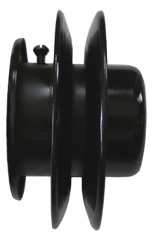
Side view of hub |

The 8 hex bolts plus the |

Spindle Bearing |

Impeller & Shaft assy |
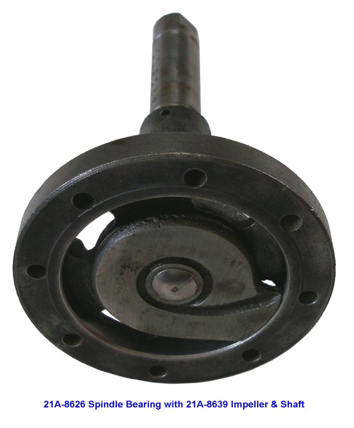
Spindle Bearing |
 Fan hub shown from |
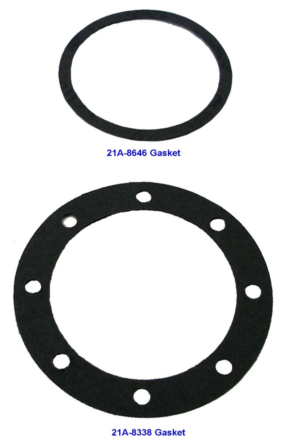
Fan hub gaskets |
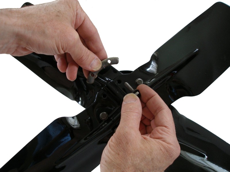
Assembly of fan to hub |

Tightening fan bolts |
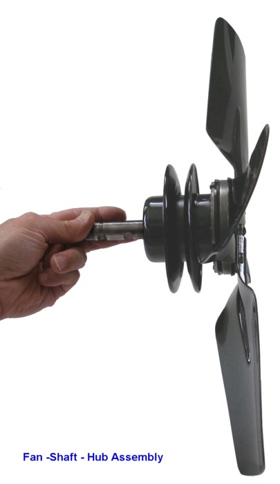
The completed fan-hub-shaft assembly |
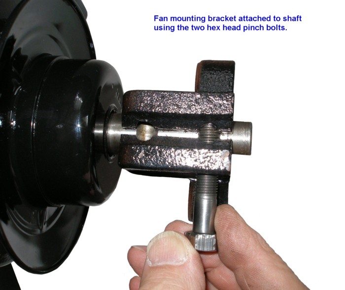
Attaching the mounting bracket |
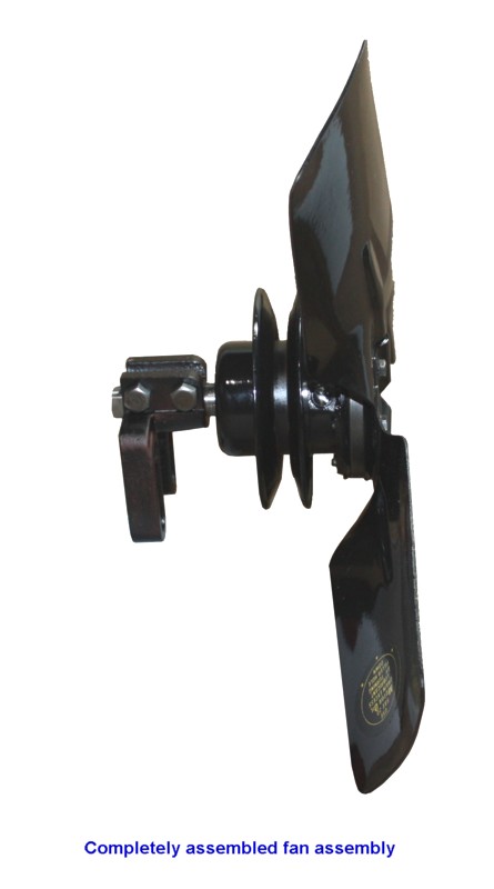
The completed fan-hub-shaft assembly |
|||
|
|
|||||